Labels

Saturday 30 June 2012

Blow Molding (BM) Process

Today, when walking in your supermarket, it is increasingly difficult to find items packed in glass and jars.  Packaging for soft drinks, healthcare and beauty products, household chemicals and medicines, among other products, have switched from glass or metal to plastics.  Today the Blow Molding industry has expanded from simple plastic containers to plastic drums, gas tanks, automobile parts and toys in all shapes and sizes.
01-blow-molding-extrusion blow molding-injection blow molding-parison extrusion
Blow Molding (BM) process makes it possible to manufacture molded products economically, in unlimited quantities, with virtually no finishing required.  The basic process of blow molding involves a softened thermoplastic hollow form which is inflated against the cooled surface of a closed mold.  The expanded plastic form solidifies  into a hollow product. 
Blow molded components are now seen all over the markets and industries for traditional materials, particularly in liquid packaging applications.  The last few decades saw the introduction of  Poly Ethylene (PE) squeeze bottles for washing liquids, Poly Vinyl Chloride (PVC) for cooking oil and fruits squash bottles, and Poly Ethylene Terephthalate (PET) for carbonated beverage bottles.  Nowadays, it is also used for the production of toys, automobile parts, accessories and many engineering components.
There are basically four types of blow moulding used in the production of plastic bottles, jugs and jars. These four types are:
  1. Extrusion blow molding,
  2. Injection blow molding,
  3. Stretch blow molding and
  4. Reheat and blow molding.
Extrusion blow molding is perhaps the simplest type of blow molding, whereby a hot tube of plastic material is dropped from an extruder and captured in a water cooled mold. Once the molds are closed, air is injected through the top or the neck of the container; just as if one were blowing up a balloon. When the hot plastic material is blown up and touches the walls of the mold the material “freezes” and the container now maintains its rigid shape. There are various types of shuttle, reciprocating and wheel style machines for the production of extrusion blown bottles. Shuttle or reciprocating type machines can be used for small, medium and high volume production with wheel machines being the most efficient for huge volume production of certain resins.
01-petblow-plastic products manufacturing-PET Preform-PET bottles-stretch blow molding
A typical apparatus consists of following major components i.e. blow pin, plunger, accumulator and lastly a mold.
Actually the process utilizes air pressure to inflate softened thermoplastic tube which is sealed at one end (also called as parision). This parision is constantly inflated and extruded. Then later on it is cut according to required dimensions. The temperature in Accumulator is maintained around 400 degree Celsius or so.
Stretch_blow_mold-dies-PET Pre form mold-household appliance mold
The mold consists of two split parts which have a semi-circular cross-section. Usually the air pressure which is applied in low pressure molding is about 50 to 250 psi. Various forms of blow molding used in industry today on a wide scale are Injection Blow Molding.
Injection Blow Molding though not used in industry, has very limited and specific applications like making small medicine plastic bottles etc. Extrusion blow molding is the simplest form of blow molding. A tube of plastic material which is generally maintained hot, is dropped from an extruder only to be captured in a water cooled mold. Once the molds are closed, air is injected through the top or the neck of the container and the tube is inflated just like a balloon. When the hot plastic material is blown up and touches the walls of the mold the material is cooled and the container now maintains a solid, rigid shape.
Now Stretch blow molding, this process requires the raw material to be formed in a pre-form using injection molding and later on stretch blow molding process can be applied.
The product range varies from various cylindrical components like bottles, cans, floats heater ducts in automobile parts and various small pipe fittings and hollow cylindrical parts can be produced in mass production.
The advantages are many like the tooling costs are very less as compared to injection molding, the part performance is excellent under pressure. Then the products have excellent environmental stress crack resistance. The products also perform excellently in high speed impact strength than even the metal components the process can be automated and used in mass production.
The disadvantages mainly raise environmental concerns. It depends on petroleum industry as any plastic industry depends. Also the cylindrical shapes are delicate so if the dimensions are not accurate then they result in scrap.

CNC programming Basics

Interpolation
The method by which contouring machine tools move from one programmed point to the next is called interpolation. This ability to merge individual axis points into a predefined tool path is built into most of today’s MCUs.
There are five methods of interpolation:
  • linear
  • circular
  • helical
  • parabolic
  • cubic
All contouring controls provide linear interpolation, and most controls are capable of both
linear and circular interpolation. Helical, parabolic, and cubic interpolation are used by industries that manufacture parts which have complex shapes, such as aerospace parts and dies for car bodies.
Linear Interpolation
Linear Interpolation consists of any programmed points linked together by straight lines, whether the points are close together or far apart
Curves can be produced with linear interpolation by breaking them into short, straight-line segments. This method has limitations, because a very large number of points would have to be programmed to describe the curve in order to produce a contour shape. A contour programmed in linear interpolation requires the coordinate positions (XY positions in two-axis work) for the start and finish of each line segment. Therefore, the end point of one line or segment becomes the start point for the next segment, and so on, throughout the entire program.
01-example of Linear Interpolation-straight line motion of a cutter-2 axis-2 position
Circular Interpolation
The development of MCUs capable of circular interpolation has greatly simplified the process of programming arcs and circles. To program an arc, the MCU requires only the coordinate positions (the XY axes) of the circle center, the radius of the circle, the start point and end point of the arc being cut, and the direction in which the arc is to be cut (clockwise or counterclockwise)01-circular Interpolation
Codes:
The most common codes used when programming CNC machines tools are
  • G-codes (preparatory functions), and
  • M codes (miscellaneous functions).
Other codes such as F, S, D, and T are used for machine functions such as feed, speed, cutter diameter offset, tool number, etc.
G-Code
G-codes are sometimes called cycle codes because they refer to some action occurring on the X, Y, and/or Z axis of a machine tool.
01-G-Codes example-rapid transverse-Linear Interpolation-Straight line path 01-G-Codes-Circular Interpolation colockwise-Anticlockwise or Counterclockwise
Group Code Function
01 G00 Rapid Positioning
01 G01 Linear Interpolation
01 G02 Circular Interpolation  clockwise (CW)
01 G03 Circular Interpolation Counter clockwise (CCW)
06 G20* Inch input (in.)
06 G21* Metric Input (mm)
  G24 Radius Programming (**)
00 G28 Return to Reference Point
00 G29 Return from Reference Point
  G32 Thread Cutting (**)
07 G40 Cutter Compensation Cancel
07 G41 Cutter Compensation Left
07 G42 Cutter Compensation Right
08 G43 Tool length compensation positive
08 G44 Tool length compensation minus
08 G49 Tool Length Compensation Cancel
  G84 Canned Turning Cycle (**)
03 G90 Absolute Programming
03 G91 Incremental Programming
(*) – on some machines and controls, these may be G70 (inch) and G71 (metric)
(**) – refers only to CNC lathes and turning centers.
M-CODE:
M or miscellaneous codes are used to either turn ON or OFF different functions which control certain machine tool operations.
01-M-Codes-Direction of Rotation-Clockwise-Counter clockwise-Tool Change - End of program-return to beginning
Code     Function     
M00     Program stop     
M02     End of program     
M03     Spindle start (forward CW)     
M04     Spindle start (reverse CCW)     
M05     Spindle stop     
M06     Tool change     
M08     Coolant on     
M09     Coolant off     
M10     Chuck – clamping (**)     
M11     Chuck – unclamping (**)     
M12     Tailstock spindle out (**)     
M13     Tailstock spindle in (**)     
M17     Tool post rotation normal (**)     
M18     Tool post rotation reverse (**)     
M30     End of tape and rewind     
M98     Transfer to subprogram     
M99     End of subprogram     
(**) – refers only to CNC lathes and turning centers.

Infrared Curing & Drying Technology

01-infrared curing process-infrared spectrum wave-conduction, convection, radiation
The coatings and paint industries strive to provide high technology coatings while reducing volatile organic compounds and energy consumption to produce a finished coating. Conventionally Convection ovens are used to cure the coatings. But this process which uses electric heaters is not an optimal process and is associated with various disadvantages.
01-coating surface absorption-infrared energy -infrared curing
Improved technologies are available today, which can either replace or improve the convection curing process. Infrared Curing is such a technology which uses Infrared rays emitted by an Infrared emitter to provide the required cure. Infrared curing applies light energy to the part surface by direct transmission from an emitter. Some of the energy emitted will be reflected off the surface, some is absorbed into the polymer and some is transmitted into the substrate.
01-reduced cycle times on final cure-eliminating manual rack up time
This direct transfer of energy creates an immediate reaction in the polymer and cross linking begins quickly once the surface is exposed to the emitter. Infrared emitters are often custom manufactured to suit the production demand. The various aspects of Infrared curing and convection curing and the possibility of combining these two technologies into a singe system will be discussed in this seminar.
01-infrared wave-infrared heating-infrared emitter-infrared curing
How it Works
Infrared heating is a direct form of heating. The source of the heat (the infrared emitter or lamp) radiates: energy that is absorbed by the product directly from the emitter. That is, the heat energy is not transferred through an intermediate medium. This is one reason for  the  inherent high-energy efficiency of infrared systems. For  example, hot air heating  first needs to heat air; the air then heats the product by convection.
01-infrared emitter-infrared curing systems
Infrared  energy is directed  to  the  product. When  the  product absorbs this energy, it is then converted into heat. Infrared energy is dispersed from the source in much the same  way as visible light. Exposed product surfaces easily absorb  the  infrared  energy and  become  heated. Therefore, heating effectiveness is related to line-of-sight between the source and the product. Depending on the coating and/or product substrate material, this heat is further thermally conducted.
01-table-characteristics of commercially used infrared heat sources
The ability of the product to absorb energy is also known as its “emissivity”. A theoretical body that absorbs all energy is termed a “black body”. A black body has an emissivity of 1. A highly reflective body would have a low emissivity value, approaching 0. (Reflectivity is the inverse of emissivity).
The potential of a product to become heated with infrared is related to the following:
• Watt density (total output power) of the source
• Wavelength (temperature) of the source
• Distance from the source to the product
• Reflective characteristics of the oven cavity
• Air movement and temperature in the oven
• Time product is exposed to the source
• Ratio of exposed surface area to the mass of the product
• Specific heat of the product
• Emissivity of the product
• Thermal conductivity of the product
CURING
Curing is a process of baking surface coatings so as to dry them up quickly. Curing is a broad term which means all the techniques employed for the finishing operations incurred during part production. Curing essentially involves either the melting of the coating or evaporation of volatile fluids present in the coating by the application of heat energy.
Curing is given to a wide range of materials both organic and inorganic. Usually curing is given to materials like ,
" Paints
" Enamel
" Liquor
" Powder coatings
" Varnishes
" Epoxy coatings
" Acrylic coatings
" Primers Etc.
Curing is also given to Rubber and Latex .The principle used for curing can also be used for drying rice and grains.
01-infrared technology-infrared-convection systems-tunnel system
CONVECTION CURING
Convection ovens are usually used for curing purposes. Traditional convection ovens use heated forced air to provide the necessary cure. Convection ovens consist of a chamber lined on the inside with Electric heaters. The shape of the chamber will be in accordance to the shape or geometry of the part being cured. A series of blowers circulate the heated air around providing the required cure. This process depends on convection to transfer heat from hot air to body surface and conduction to transfer heat to the interior of the surface. The air being delivered is held at temperature using closed-loop control, which provides predictable, repeatable results. Typically a temperature of around 250-500 degree Fahrenheit is required for paint or powder. Though convection ovens are widely used today they have certain disadvantages, which chokes the overall productivity of a company
Disadvantages of convection ovens :
" Fairly long heating times:-
Convection is a slow process. It takes a considerable amount of time for the heaters to heat up and raise the temperature of air to the required level. This causes a lag in the process and hence the curing time increases. Longer curing time spells reduced assembly line movement. This in turn reduces productivity.
" High energy consumption:-
A convection column dryer uses around 2000 BTU(British Thermal Unit) of energy to remove 1 pound of moisture. They use around 7.7 KW of electrical energy to dry a ton of rice. These are significantly larger figures for any company trying to bring energy consumption under control. The additional use of blowers and compressors further increases energy consumption.
" Large floor area required:-
Convection ovens are bulky in nature. Due to the presence of compressors and blowers, additional space is needed, which in turn increases the floor area requirement.
" Air circulation is required:-
Convection heating requires a medium for transmission of heat. Hence blowers are employed for good circulation of heated air. This increases the overall cost of the equipment.

Computer Numerical Control (CNC)

The term numerical control is a widely accepted and commonly used term in the machine tool industry. Numerical control (NC) enables an operator to communicate with machine tools through a series of numbers and symbols.
NC which quickly became Computer Numerical Control (CNC) has brought tremendous changes to the metalworking industry. New machine tools in CNC have enabled industry to consistently produce parts to accuracies undreamed of only a few years ago. The same part can be reproduced to the same degree of accuracy any number of times if the CNC program has been properly prepared and the computer properly programmed. The operating commands which control the machine tool are executed automatically with amazing speed, accuracy, efficiency, and repeatability.
The ever-increasing use of CNC in industry has created a need for personnel who are knowledgeable about and capable of preparing the programs which guide the machine tools to produce parts to the required shape and accuracy. With this in mind, the authors have prepared this textbook to take the mystery out of CNC – to put it into a logical sequence and express it in simple language that everyone can understand.
01-CNC lathe - CNC Turning Center-Cartesian Coordinate System
image
 01-cost-effective-2-axis-cnc-lathes-computer numeric control
Milling Machine
The milling machine has always been one of the most versatile machine tools used in industry (Fig. 5). Operations such as milling, contouring, gear cutting, drilling, boring, and reaming are only a few of the many operations which can be performed on a milling machine. The milling machine can be programmed on three axes:
• The X axis controls the table movement left or right.
• The Y axis controls the table movement toward or away from the column.
• The Z axis controls the vertical (up or down) movement of the knee or spindle.
01-3 axis - vertical Machining center-CNC Machining Center The main axes of a vertical machining center.
01-Cnc-Milling-Machines-milling, contouring, gear cutting, drilling, boring, and reaming

Friday 29 June 2012

Latest Petrol Price Update: Might Go down by as Much as Rs 4/Litre


A few days back we shared that prices of petrol might be reduced a couple of rupees but it did not happen. The reason provided by oil companies was the dying value of rupee.
However, international crude rates have gone to their lowest level since December 2010 and there is ample amount of room for a hefty price cut on petrol. Petrol costs per barrel have reduced to around 97 dollars from $115 earlier.
There is scope for as much as Rs 4 reduction on per liter of petrol currently, however, with the falling rupee cost of imports might again increase. Hence, companies are keeping an eye on the condition and a decent amount of price reduction is definitely expected starting July 1.

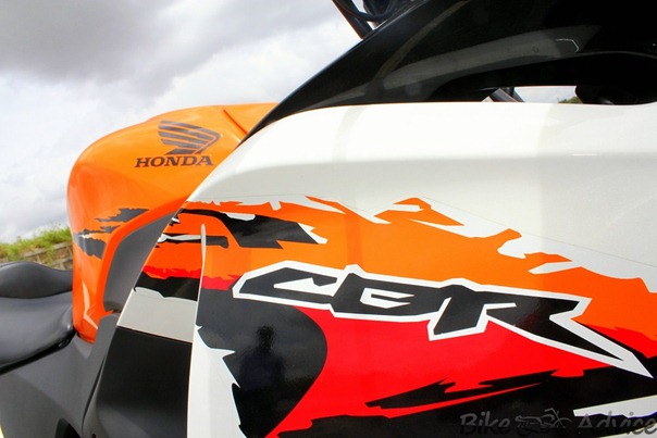
Honda CBR150R 2012 India Road Test and Review: Coming Soon


Honda CBR150R India
Today, Sharat Aryan of our team got his hands on this 150cc beast for BikeAdvice exclusive test ride and as we speak he is penning down the review of Honda CBR150R bike, he did send us some pictures to drool over until the review is complete, find them below.

Honda CBR150R Pics: click on the pics to enlarge.
Honda CBR150R motorcycle
Honda CBR150R-2012
Honda CBR150R-review
In his words:
The bike seems to be very impressive, here are a few teaser photos from the road test.

Tuesday 26 June 2012

Vision Gauge Digital Optical Comparator

01-horizontal vision gauge digital optical comparator-horizontal standard type-optical measuring system-DC 3000 data processing system
The Vision Gauge Digital Optical Comparator is "The Fastest, Easiest, Most Accurate Way to Compare a Part to a CAD File. Vision Gauge Digital Optical Comparators are very robust. They are perfect for both the shop floor and the Quality Control lab. Standard 12" travel X-axis stage with 0.5 micron resolution encoder and protective bellows around the 6" travel Y-axis column. All 3 axes (X, Y and Z) have high-accuracy crossed roller movements for optimal linearity and positional repeatability and high load carrying capability. Hard chrome plated X-axis stage, made of hardened tooling steel and with dual industry-standard dovetail grooves for easy part fixturing.
02-vertical vision gauge digital optical comparator-vertical standard type-optical measuring machine-optical comparator
Vision Gauge Digital Optical Comparators are complete, ready-to-run Windows-based solutions and  are  delivered network-ready. They are available in both horizontal and vertical configurations. They have industry standard dovetail mounting grooves for easy part fixturing.
Vision Gauge Digital Optical  Comparators are available  with transmitted (i.e. back) and / or reflected (i.e. front) illumination.  All  illumination  is  LED-based for very stable and repeatable illumination  conditions  over  a  very  long  life  (no  more  bulbs  to replace!). Furthermore, the illumination is programmable and computer-controlled. Everything is done through a single simple an d intuitive software interface.
01-vice with angle-accessories for digital optical comparator
Vision Gauge Digital Optical  Comparators have power focus. They are available in industry standard 5X, 10X, 20X,  50X  and 100X  optical configurations.  They are available in both single and multi-mag configurations.
01-rotary table-accessories for digital optical comparator
Vision Gauge Digital Optical Comparators and extremely easy to use. They are a "drop in" replacement for traditional optical comparators. An optional high-resolution LASER module is also available for depth & height measurements. Motorized fixtures and extended travels are also available.
Benefits:
  • Produce a very high contrast image with very sharp edge profiles so that there is no problem viewing it in full daylight.
  • Are much more accurate
  • Allow the user to be much more productive and get more work done with a single machine
  • Have "Auto Pass / Fail"
  • Can compute and display the part’s deviation from nominal and compare it to bi-directional tolerances
  • Work directly with the CAD data so that no overlays / templates / Mylars are required
  • Can be used to collect images (either with or without the CAD data overlay and with or without annotations), measurements and data .
  • Can also carry out fully automated measurements (like a video CMM)
  • Have a smaller footprint and use less floor space
  • Can be moved much more easily and without requiring re-calibration (i.e. “rolling cart” configuration is standard)
  • Have a much greater optical depth of field, i.e. “everything is in focus all at once”
  • Have a longer optical working distance ( i.e. more clearance between the part and the lens)
  • Allow you to compare a part to its CAD data beyond the optical field-of-view ! (because the CAD data tracks the part and follows the stage motion )
  • Have LED illumination for very stable illumination over a 10 year life. No more bulbs to change
01-vertical beam optical comparator-vertical vision gauge digital optical comparator-horizontal standard type-optical measuring system-DC 3000 data processing system

Finite Element Analysis - List Of FEA Software’s

01-Finite element analysis-gear-meshing-analysis of gear meshing, Find gear force, find power transmission
Finite Element Analysis (FEA) is a computer simulation technique used in engineering analysis. It uses a numerical technique called the finite element method (FEM). In this, the object or system is represented by a geometrically similar model consisting of multiple, linked, simplified representations of discrete regions — finite elements. Equations of equilibrium, in conjunction with applicable physical considerations such as compatibility and constitutive relations, are applied to each element, and a system of simultaneous equations is constructed. The system of equations is solved for unknown values using the techniques of linear algebra or nonlinear numerical schemes, as appropriate.
FEA has become a solution to the task of predicting failure due to unknown stresses by showing problem areas in a material and allowing designers to see all of the theoretical stresses within. This method of product design and testing is far superior to the manufacturing costs which would accrue if each sample was actually built and tested.
01-bogey analysis-finite element results-von mises analysis results-stress analysis
There are generally two types of analysis: 2-D modeling, and 3-D modeling. While 2-D modeling conserves simplicity and allows the analysis to be run on a relatively normal computer, it tends to yield less accurate results. 3-D modeling, produces more accurate results while it can only be run satisfactorily on a faster computer effectively. Within each of these modeling schemes, the programmer can insert numerous algorithms (functions) which may make the system behave linearly or non-linearly. Linear systems are far less complex and generally do not take into account plastic deformation. Non-linear systems do account for plastic deformation, and many also are capable of testing a material all the way to fracture.
While being an approximate method, the accuracy of the FEA method can be improved by refining the mesh in the model using more elements and nodes, though this will retard the process of converging.

Uses


A common use of FEA is for the determination of stresses and displacements in mechanical objects and systems. It is used in new product design, and also in existing product refinement. A company is able to verify whether a proposed design will be able to perform to the client’s specifications prior to manufacturing or construction. Modifying an existing product or structure is utilized to qualify the product or structure for a new service condition. In case of structural failure, FEA may be used to help determine the design modifications to meet the new condition. However, it is also routinely used in the analysis of many other types of problems, including those in heat transfer, fluid dynamics and electromagnetism. FEA is able to handle complex systems that defy closed-form analytical solutions.

Some FEA Software’s


Free/Open Source


  • ALBERTA
    An adaptive hierarchical finite element toolbox

  • CalculiX
    • is an Open Source FEA project. The solver uses a partially compatible ABAQUS file format. The pre/post-processor generates input data for many FEA and CFD applications.

  • Code Aster:

    French software written in Python and Fortran, GPL license.
  • Deal.II
    is a finite element differential equation library
  • DUNE,
    Distributed and Unified Numerics Environment GPL Version 2 with Run-Time Exception, written in C++
  • Elmer FEM solver:
    Open source multiphysical simulation software developed by Finnish Ministry of Education’s CSC, written in C, C++ and Fortran
  • FEAPpv
      A general purpose finite element analysis program
  • FEBio
    Finite Elements for Biomechanics
  • FEMM
    is a Windows finite element solver for 2D and axisymmetric magnetic, electrostatic, heat flow, and current flow problems
  • FEMPACK
    – Finite Element Routines
  • FEniCS
    Project: a LGPL-licensed software package developed by American and European researchers
  • FETK
    is an adaptive finite element method (AFEM) software libraries and tools for solving coupled systems of nonlinear geometric partial differential equations (PDE)
  • FRANC2D and FRANC3D:
    is a two/three dimensional, finite element based program for simulating curvilinear crack propagation in planar (plane stress, plane strain, and axisymmetric) structures developed by Cornell Fracture Group US. software available for Windows and Linux/UNIX
  • Freefem++
    is an implementation of a language dedicated to the finite element method
  • GetFEM++
    An open-source finite element library
  • Hermes Project:
    Modular C/C++ library for rapid development of space- and space-time adaptive hp-FEM solvers.
  • Impact:
    Dynamic Finite Element Program Suite, for dynamic events like crashes, written in Java, GNU license
  • libMesh
    a framework for the numerical simulation of partial differential equations
  • OFELI :
    (Object Finite Element LIbrary)a library of finite element C++ classes for multipurpose development of finite element software
  • OOF:
    finite element modeling for material science
  • OOFEM:
    Object Oriented Finite EleMent solver, written in C++, GPL v2 license
  • OpenFOAM
    (Field Operation And Manipulation). Originally for CFD only, but now includes finite element analysis through tetrahedral decomposition of arbitrary grids.
  • OpenSees
    is an Open System for Earthquake Engineering Simulation
  • ParaFEM
    is a freely available, portable library of subroutines for parallel finite element analysis. The subroutines are written in FORTRAN90/95 and use MPI for message passing.
  • WARP3D
    Static and Dynamic Nonlinear Analysis of Fracture in Solids
  • Z88:
    FEM-software available for Windows and Linux/UNIX, written in C, GPL license

Proprietary/Commercial


  • Abaqus:
    Franco-American software from SIMULIA, owned by Dassault Systemes
  • ADINA
  • Advance Design BIM
    software for FEM structural analysis, including international design eurocodes, a solution developed by GRAITEC
  • ALGOR
    Incorporated
  • Altair HyperWorks
    Altair Engineering’s HyperWorks is a computer-aided engineering (CAE) simulation software platform that allows businesses to create superior, market-leading products efficiently and cost effectively.
  • ANSA:
    An advanced CAE pre-processing software for complete model build up.
  • ANSYS:
    American software
  • COMSOL Multiphysics
    COMSOL Multiphysics Finite Element Analysis Software formerly Femlab
  • Creo Elements / Pro Mechanica:
    A p-version finite element program that is embedded in the MCAD application Creo Elements Pro, from PTC (Parametric Technology Corporation)
  • Diffpack
    Software for finite element analysis and partial differential equations
  • Diana
    (software) a multi-purpose finite element program (three-dimensional and nonlinear) by TNO
  • Falcon2.0 :
    Lightweight FEM POST Processor and Viewer for 3D UNV and NASTRAN files
  • FEFLOW:
    simulates groundwater flow, mass transfer and heat transfer in porous media
  • Femap,
    Siemens PLM Software: A pre and post processor for Windows
  • FEM
    -Design Structural analysis software from StruSoft (Swedish company).
  • FEMtools,
    Dynamic Design Solutions: A toolbox for static and dynamic simulation, verification, validation and updating of finite element models. Includes also modules for structural optimization and for obtaining experimental reference data.
  • FENSAP-ICE
    (Finite Element Navier–Stokes Package) the fully-integrated 3D in-flight CFD icing simulation system developed by Newmerical Technologies Intl.
  • FlexPDE
  • Flux :
    American electromagnetic and thermal FEA
  • Genie:
    DNV (Det Norske Veritas) Software
  • HydroGeoSphere:
    A 3D control-volume finite element hydrologic model, simulating surface and subsurface water flow and solute and thermal energy transport
  • HyperSizer:
    Software for composite material analysis
  • Infolytica MagNet :
    North American electromagnetic, electric and thermal FEA software
  • JMAG:
    Japanese software Actran: Belgian Software (Acoustic)
  • LINKpipe:
    from LINKftr AS (Norwegian company). Special purpose non linear FE program for pipelines
  • LS-DYNA
    LSTC – Livermore Software Technology Corporation
  • LUSAS:
    UK Software
  • MADYMO:
    TASS – TNO Automotive Safety Solutions
  • MSC.Marc:
    from MSC Software
  • Nastran:
    American software, from MSC Software
  • Nautics 3D Beam:
    DNV (Det Norske Veritas) Software
  • Nastran/EM
    Nastran Suit for highly advanced Durability & NVH Analyses of Engines; born from the AK32 Benchmark of Audi, BMW, Daimler, Porsche & VW; Source Code available
  • NEi Fusion, NEi Software:
    3D CAD modeler + Nastran FEA
  • NEi Nastran, NEi Software:
    General purpose Finite Element Analysis
  • NEi Works, NEi Software:
    Embedded Nastran for SolidWorks users
  • NISA:
    Indian software
  • PAK:
    Serbian software for linear and nonlinear structural analysis, heat conduction, fluid mechanics with heat transfer, coupled problems, biomechanics, fracture mechanics and fatigue.
  • Plaxis:
    Geotechnical 2D/3D FE suites, with support for stresses, deformations, groundwater flow and dynamics.
  • PZFlex:
    American software for wave propagation and piezoelectric devices
  • Quickfield :
    Physics simulating software
  • Radioss:
    A linear and nonlinear solver owned by Altair Engineering
  • Range Software:
    Multi physics simulation software
  • RFEM
  • SAMCEF:
    CAE package developed by the Belgian company
  • SAP2000:
    American software
  • STRAND7:
    Developed in Sydney Australia by Strand7 Pty. Ltd. Marketed as Straus7 in Europe.
  • StressCheck
    developed by ESRD, Inc (USA) emphasizing solution accuracy by utilizing high order elements
  • Vector Fields Concerto:
    UK 2d/3d RF and microwave electromagnetic design software
  • Vector Fields Opera:
    UK 2d/3d Electromagnetic and multi-physics finite element design software
  • Vflo:
    Physics-based distributed hydrologic modeling software, developed by Vieux & Associates, Inc.
  • Zébulon:
    French software

Poisson’s Ratio - Basics Of Mechanical Engineering

01-PoissonRatio-isotropic linearly material-youngs modulus, bulk modulus, shear modulus, auxetic materials
When an element is stretched in one direction, it tends to get thinner in the other two directions. Hence, the change in longitudinal and lateral strains are opposite in nature (generally). Poisson’s ratio ν, named after Simeon Poisson, is a measure of this tendency. It is defined as the ratio of the contraction strain normal to the applied load divided by the extension strain in the direction of the applied load. Since most common materials become thinner in cross section when stretched, Poisson’s ratio for them is positive.
For a perfectly incompressible material, the Poisson’s ratio would be exactly 0.5. Most practical engineering materials have ν between 0.0 and 0.5. Cork is close to 0.0, most steels are around 0.3, and rubber is almost 0.5. A Poisson’s ratio greater than 0.5 cannot be maintained for large amounts of strain because at a certain strain the material would reach zero volume, and any further strain would give the material negative volume.
01-poissons ratio-calculate simple stress and strains-engineering mechanics
Some materials, mostly polymer foams, have a negative Poisson’s ratio; if these auxetic materials are stretched in one direction, they become thicker in perpendicular directions.Foams with negative Poisson’s ratios were produced from conventional low density open-cell polymer foams by causing the ribs of each cell to permanently protrude inward, resulting in a re-entrant structure.
An example of the practical application of a particular value of Poisson’s ratio is the cork of a wine bottle. The cork must be easily inserted and removed, yet it also must withstand the pressure from within the bottle. Rubber, with a Poisson’s ratio of 0.5, could not be used for this purpose because it would expand when compressed into the neck of the bottle and would jam. Cork, by contrast, with a Poisson’s ratio of nearly zero, is ideal in this application.
01-poissons ratio-strain changes
It is anticipated that re-entrant foams may be used in such applications as sponges, robust shock absorbing material, air filters and fasteners. Negative Poisson’s ratio effects can result from non-affine deformation, from certain chiral microstructures, on an atomic scale, or from structural hierarchy. Negative Poisson’s ratio materials can exhibit slow decay of stress according to Saint-Venant’s principle. Later writers have called such materials anti-rubber, auxetic (auxetics), or dilatational. These materials are an example of extreme materials.

Graphene -The Material Of The Future

       01-graphene-a ultra thin material-graphene extraction from graphite-tracing graphene from graphite-graphite_pencil The graphene is a substance which has a single-layer crystal lattice of carbon atoms, which is unusual since it is different from all of the materials of its kind. Several researchers have identified a way of making this substance, which allows them to use it in various fields and especially for the high-speed electronic devices.
01-graphene layer-graphene lattice parameters-graphene growth-Graphene_from_gases_for_new,_bendable_electronics_
Graphene Definition:
Graphene is defined as a one atom thin sheet of carbon atoms arranged in a Hexagonal format or a flat monolayer of carbon atoms that are tightly packed into a 2D honeycomb lattice.
01-graphene hexagonal layer-graphene lattice parameters-graphene growth
History:
In October 2010, two University of Manchester (U.K.) scientists, Andre Geim and Konstantin Novolselov, were awarded the 2010 Nobel Prize in physics for their research on graphene. Graphene is a one-atom-thick sheet of carbon whose strength, flexibility, and electrical conductivity have opened up new horizons for high-energy particle physics research and electronic, optical, and energy applications.
01-flexible graphene sheet-with silver electrodes printed on it-touch screen graphene sheets-transparent electrodes-flexible transparent electronics
Graphene properties:
Graphene oxide, a single-atomic-layered material made by reacting graphite powders with strong oxidizing agents, has the ability to easily convert into graphene a low-cost carbon-based transparent and flexible electronics.
Graphene Oxide:
Graphene oxide has been known in the scientific world for more than a century and was largely described as hydrophilic, or attracted to water. These graphene oxide sheets behave like surfactants, the chemicals in soap and shampoo that make stains disperse in water.
01-mechanosynthesis-graphene bonding-graphene scaling-graphene sheet material formation-graphene zipper like bond rearrangement-graphene_into_nanotube
Mechanical Properties:
Young’s Modulus:
01-various material properties-Youngs modulus of different materials-Graphene properties
01-graphene electrical properties-graphene electrical conductivity-1000 times faster than silicon-bendable graphene battery concept-flexible-graphene-battery-concept
1. Graphene sheets stack to form graphite with an interplanar spacing of 0.335 nm, which means that a stack of 3 million sheets would be only one millimeter thick.
2. Graphene is a Zero Gap Semiconductor. So it has a high electron mobility at room temperature. It’s a Superconductor. Electron transfer is 100 times faster then Silicon.
3. Graphene has a record breaking strength of 200 times greater than steel, with a tensile strength of 130GPa.
4. Graphene can be used to create circuits that are almost superconducting, potentially speeding electronic components by as much as 1000 times.
5. Graphene electrodes used in lithium-ion batteries could reduce recharge times from two hours to about 10 minutes.
Graphene Production:
01-chemical vapor deposition techniques-chemical vapour deposition-CVD -graphene production-graphene fabrication-discovery of graphene
Chemical Vapor Deposition (CVD) and Molecular Beam Epitaxy (MBE) are two other potential routes to Graphene growth.
Applications:
01-graphene applications-graphene touch pad electronics gadgets-touch phones made from graphene-graphene technology-flexiphone
  • New devices like Touch screens, Micro Displays and Monitors
  • Chip Making, Circuit Designs
  • Solar cells
  • Micro Fuel Cells
  • Air Bag Deployment Systems and Gyroscopes in Car Electronic Stability Control
  • Pressure Sensors, Micro Tips & probes

SolidWorks COSMOS Simulation

01-design challenges in the automotive sector-product design-surface design-new product development-FEA solutions-concept design
Design Validation:
  • Accelerate new product development
  • Switch to alternate or cheaper material
  • Reduce Prototyping costs
  • Improve product quality and performance
  • Enhance reliability
01-design validation need-Solidworks COSMOS design validation-engineering design challenges
Responding To Design Challenges:
  • Improve complex product designs
    • Enhanced function and performance
    • Meet product specification and / or regulation
01-life cycle simulation-CAE-multi body dynamics-flexible body-Product life cycle management-PLM software-Solidworks-COSMOS-design optimization-FE modeling
  • Reduce Re-Design
    • Design right first time
    • Weight and shape optimization
  • Early problem detection and correction
    • Avoid field failures
    • Study alternative designs
  • Greater product quality
    • Efficient and reliable
    • Reduced liability
CAE Solutions:
01-validate design with FEA-Finite Element Analysis-Design optimization-verify design function and intent-FEM
  • Development of indigenous technologies and products
  • Enumeration of methods for Analysis to test correlations
  • Procedure for Failure mode and Prediction and Life Calculations
  • Value Addition and Value Engineering (VAVE)
  • Reduction in Cost and Product development time
  • Elimination of Performance problems
  • Improvement in performance efficiency
COSMOS Salient Features:
01-design validation software-Solidworks-cosmos simulation-FEA Analysis-Stress Analysis-Finite Element Analysis-Simplify Design analysis
  • Theory in Finite Element Analysis including procedure for performing FEA
  • Practical solution to complex problems involving multi-domain interaction
  • Correlation to real world problems and phenomena
  • Advanced training on Fatigue, Non-Linear FEA and Vibrations
Why COSMOS for Design Validation:
01-solidworks-cosmos-design star-solidworks simulation-cosmos fea-cosmosworks-cosmos design validation
  • CAD Integrated Design validation
  • Easy to use and Shorter Learning Curve
  • Evaluate multiple Design scenarios in one stroke
  • Integrated Kinematic Analysis using Cosmos Motion
  • Seamless transfer of loading from COSMOS Motion to COSMOS  Works for FEA
  • Multi Domain Analysis in Integrated CAD Environment
SolidWorks / COSMOS Simulation benefits:
  • Easy-to-Use Simulation toolset – Enables designers to concentrate on designs not tools
  • Automatic Report Generation
  • Multiple configurations of designs can be studied automatically – enables Design of Experiments
  • Unlimited Model size – limited only by Computational resources
  • True Contact simulation for accurate load transfer
  • Sensors and Probes to compare results with Real-World Test Data
  • Fast, Accurate and Reliable – Backed by almost 3 Decades of experience

RT Prototyping - Rapid Tooling

An Application of Rapid prototyping is Rapid tooling, this an automatic fabrication of machine tools. Tooling is one of the most costly steps in the manufacturing process.
01-rapid tooling-RT Rapid prototyping-Mold making examples in rapid prototyping
Tools are often complex and need to be wear resistant for production. To meet these requirements, molds and dies are traditionally made by CNC machining, EDM or other methods. All traditional methods are expensive and time consuming; making rapid tooling prototyping the desired alternative. Many believe tooling and design cost may be cut by 50% to 70% by using rapid prototyping.
Rapid tooling is divided in two categories; indirect tooling and direct tooling.
Indirect Tooling
01-indirect tooling-Rapid tooling types
Most rapid tooling today is indirect tooling. Rapid prototyping parts are used as patterns for making molds and dies. These models can be in the following manufacturing processes.
  • Investment Casting
01-investment-casting of parts
Some rapid prototyping can be used as investment casting patterns. Patterns must retain size when heated and not crack during the finishing process.
  • Injection Modeling
01-injection moulding-plastic moulding
A Stereo lithography machine is used to make a match-plate pattern of the desired molding. To form this mold it is plated with metal material such as nickel; then reinforced with ceramic. The two halves are separated to remove the pattern, leaving a perfect model capable to producing thousands of injection models.
  • Sand Casting
01-Green_Sand-casting-the traditionla method of casting cylinder blocks
A rapid prototyping model is used as a pattern which sand mold or “casting” is built. (make the following link) Laminated Object Manufacturing (LOM) machines can be used for this process. A LOM model can produce nearly 100 sand molds.
  • Vacuum Casting
01-vacuum-casting-process-fundamentals of metal casting process
The oldest and simplest rapid tooling prototyping technique; a pattern is suspended in a vat of liquid silicon. When the material cures, the pattern may be removed. The silicon molds can produce 15 or more patterns.
Direct Tooling
01-direct tooling-types of rapid tooling
To make metal tooling direct from CAD file through rapid prototyping process; is the answer to every production engineers dream.
  • Rapid tool
A process which uses SLS to sinter  poly- coated steel pellets together to produce metal mold.
  • Laser Engineering Net Shaping (LENS) –          
01-laser engineering net shaping-LENS
A process that can create metal tools directly from a CAD file. This process is capable of using multiple materials, stainless steel, HSS, tungsten carbide as well as others. A laser beam melts the top layer of the part in areas where material is to be added until the part is complete. Unlike sintering, LENS does produce a solid metal part since the metal was melted.
  • Direct AIM
01-Direct AIM-investment casting parts-RTV Molding
Another technique provided by 3D Systems of Valencia, Ca. Stereo lithography produced cores are used with traditional metal molds for injection moldings from HDPE, Polystyrene, polypropylene and ABS.
  • LOM Composite
01-laminated object manufacturing-lom_process
A method of using ceramic composite material for Laminated Object Manufacturing.
  • Sand Molding
01-sand molding-shell-mold-casting
A rapid prototyping technique that constructs sand molds directly from a CAD file.